Contact us

Shengshihuating No.76 Huai’an Road, Qiaoxi District, Shijiazhuang, Hebei, China

Tel:  +86-0311-87542365  

Fax: +86-311-67909680

E-mail: seva@sevaelec.com 

Principle

(1.) QUARTZ MATERIAL AND FREQUENCY CONTROL PRODUCTS

Quartz, a kind of crystallized Silicon Dioxide, SiO2, 32 symmetry group of trigonal system (Fig.1), exhibits piezoelectric property, which is the operating base of the electromechanical products. With its intrinstic high Q-value, the quartz based resonator and oscillator are the most wildly adopted as the reference signal source in circuitry for frequency control applications. Quartz frequency control products can be categorized into bulk acoustic wave application devices, such as crystals/resonators, monolithic crystal filters and clock oscillators, and surface accoustic wave application devices, such as SAW resonators and SAW filters. A piece of quartz crystal in a specific orientation cut, shape and dimensions is named crystal wafer (blank). Such a crystal wafer with two deposited electrodes on both sides and housed in a holder is a crystal unit (one-port resonator). By using the one-port resonators as impedance elements, crystal bandpass filters can be obtained. By incorporating the crystal resonator into a kind of electric circuit, one could get different kind of clock crystal oscillators (CXO), for example, Pierce Oscillator, Colpitts Oscillator, Simple Package Crystal Oscillator, Voltage Controlled Crystal Oscillatos, Temperature Compensated Crystal Oscillator, Oven Controlled Crystal Oscillator, and so on. Instead of bulk vibration of quartz crystals, a shorter wavelength (higher frequency) vibration can be achieved by surface wave propergation with inter-digital-transducer (IDT) electrodes on the surface of quartz material. This vibration mechanism can be used for resonator and filter applications

(2.) PIZEOELECTRICITY

The Silicon Dioxide atom is electrical natural in stable state. The electric dipole is along with silicon asix. Figure (2a) shows simplified two dimensional structure. When we apply an electric field along with dipole direction, with positive charged at the silicon side and negative charged at the oxygen side, the oxygen ions will repel to each other creating an induced electrical field to balance the system. The oxygen ions will toward to each other if we apply a negative charged and positive charged electric field to silicon and oxygen ions respectively. The oxygen ions will vibrate along horizontal direction in the same frequency as the alternative electric field along with vertical direction. The displacement of ions or the amplitude of vibration depends on the angle between the electrical field and the electric dipole of quartz. In practical three dimensional quartz crystals, electrical field is supplied by electriodes coated on the surface of quartz wafer. The orientatin of dipole can be decided through different kinds of cutting angles for quartz bar.

(Fig. 2) Simplified one dimensional piezoelectricity of SiO2

(3.) TYPE OF QUARTZ CRYSTAL CUT

According to different cut angles to quartz bars, there are different kinds of quartz plates, for examples, AT-, BT-, CT-, DT-, NT-, GT- cut plates Different types of quartz cuts, indicated by a set of Euler angles, have different available elastic, piezoelectric and dielectric properties, which are the basic parameters for designing a quartz crystal device. The most often used Quartz-cut types are shown in﹝Fig. 3﹞ schematically.

﹝Fig. 3﹞Orientation angle of a Z-plate quartz crystal.

(4.) MODE OF VIBRATION

The vibration modes of the quartz crystal units are grouped into flexure, extension, face shear and thickness shear modes. The schematics of the vibration modes and the plate cuts usually used are listed in Table 1. Fundamental mode and overtone modes can be operated in any kinds of resonators. Fundamental mode is most often used, but for the thickness type devices the overtone modes are often used as well, as shown in (Table 1)

﹝Table 1﹞Vibration Mode and Cut Angle.

(5) FREQUENCY-TEMPERATURE CHARACTERISICS

Most of the quartz products are used as an electrical circuit component for frequency selection and/or frequency control, so the frequency-temperature characteristic of the devices is the most important parameter. This parts per million (ppm) level stability of frequency-temperature characteristic is another merit of quartz frequency device that LCR discret component oscillation circuitry can not be achieved in mass-production scale. For the usually used quartz crystal cuts, their frequency-temperature characteristics are shown in (Fig. 4).

(Fig. 4) Frequency-temperature characteristics of various quartz cuts.

AT-cut is the most popular crystal cut in the quartz devices for MHz applications. (Fig. 5) shows the orientation of AT plat from top view of + X-axis.

( Fig.5 ) Orientation of AT plat

(Fig. 6) shows the frequency-temperature characteristics of the AT-cut crystal operating in thickness-shear mode, with the cut angle deviation as a parameter. It is shown that AT-cut quartz has excellent frequency stability over a wide temperature range since the first-and second-order of the temperature coefficients go to zero in this range and the temperature coefficient is only dominated by a third-order function of the temperature deviation.

△fs (i) = A1 (Ti –25)3 + A2 (Ti –25)2 + A3 (Ti –25) + A4

(Fig. 6) AT - cut frequency-temperature characteristics.

(6) EQUIVALENT CIRCUIT OF A CRYSTAL RESONATOR

(Fig. 7) shows the schematic of both metal can type and ceramic SMD type resonators and its symbol. The electrical properties of the unloaded resonator can be approximately expressed in Butterworth-Van Dyke (BVD) equivalent circuit as shown in Fig.5 when operating near a resonance frequency zone.

By using the four parameters shown in (Fig .8) the major electrical properties of a crystal resonator and of a oscillator consisting of the crystal resonator are described as follows.

﹝Fig.8﹞

(7) RESONANCE FREQUENCY

In literatures and product descriptions, there are three pairs of resonance frequencies, i,e., the "series resonance frequency" and "parallel resonance frequency", ( fs and fp ) , the "resonance frequency" and "anti-resonance" frequency, ( fr and fa ), and the "maximum and minimum total admittance located" frequencies, ( fm and fn ). All of them can be obtained from the lumped equivalent circuit parameters as given in﹝Fig.9﹞The definitions and relationship of the resonance frequency pairs can be clearly expressed in a complex admittance diagram given in (Fig. 9).

﹝Fig.9﹞ Complex Admittance of Resonator

The series and parallel resonance frequencies, fs and fp are determined by taking the input electrical conductance (real part of the admittance) and resistance (real part of the electric input impedance) in maximum, respectively, as shown in (Fig. 9). The resonance frequency, fr and anti-resonance frequency, fa , are given by the two roots where the susceptance (imaginary part of the input electric admittance) equals to zero, as shown in (Fig. 9). The resonance frequency and anti-resonance frequency fr and fa are the frequencies of principal interest in two terminal applications. For evaluating the equivalent circuit of a resonator, however, the characteristic frequencies, fs and fp are more important. They are given by

Where, C1and L1are the motional capacitance and motional inductance, respectively, and Co is the static capacitance appearing in shunt branch (Fig. 7).

(8) TERMINOLOGIES

(1) Nominal Frequency and Its Tolerance or Calibration Accuracy
The frequency of a crystal resonator is typically specified in megahertz (MHz) or kilohertz (kHz). The normal frequency is the output frequency what we expect from the crystal oscillation circuitry with proper matching. There is an amount of frequency deviation from the nominal frequency at ambient temperature (referenced to 25oC) for a real device. The tolerance of the idea central frequency deviation, as a parameter of the device, is specified with a maximum value, expressed in percent (%) or parts per million (ppm).

(2) Fundamental and Overtone Vibrations
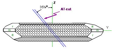
The thickness shear vibration is the main vibration mode existed in AT cut. The high order harmonic vibrations are co-existed with fundamental vibration between electrode areas. Due to the reverse polarity of two electrodes, only odd number harmonic vibrations can be excited in piezoelectric quartz resonators.

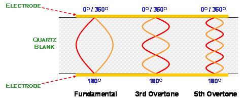
(Fig. 10) Only odd number harmonic vibrations can be excited in crystal resonator

(3) Load Capacitance
Load capacitance, CL, is the amount of capacitance that the oscillator exhibits when looking into the circuit through the two ends of the resonator. The load capacitance is formally in either series or parallel with the resonator. For parallel load case the existence of CL will affect the parallel resonance frequency and the parallel-load resonance frequency, fL, is given by

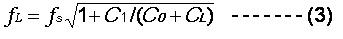
This parameter is necessary to be specified.

(4) Frequency-Temperature Stability
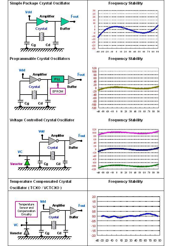
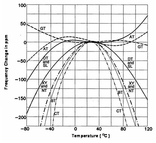
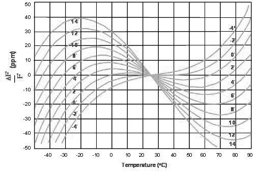
Frequency-Temperature stability is indicated by the amount of frequency variation from the value at the standard amblient temperature (25oC, usually), caused by the operating temperature change. This parameter is specified by a curve showing the frequency variation (expressed in % or ppm) versus the temperature deviation from the reference temperature (25oC). The temperature stability of a quartz device depends on the type of cut, the mode of vibration, and the dimension of the quartz blank. Besides, the deviation value is associated with the operating temperature range, the load capacitance and the drive level of the cryatal resonator.

(5) Equivalent Series Resistance (ESR)
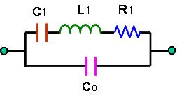
The resistance R1 appearing in the series branch (fig. 5) can be measured at series resonance frequency, where the effects of C1 and L1 are cancelled each other and the effective result of the branch is a resistive. R1 represents the mechanical loss in the crystal unit and the holder.

(6) Motional Capacitance C1 and Motional Inductance L1
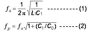
These two parameters are definitely related by the series resonance frequency, fs, as given in Eq.(1), and fs is a very sure parameter in resonator design and in characterization. Only the value of C1 is specified in industry standard and L1 can be obtained from

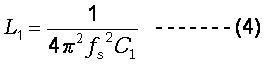
The value of C1 is very small in comparison with capacitances usually used in oscillation circuits and can be evaluated from the material and geometry parameters of the crystal plate and electrodes.

(7) Static Capacitance Co (in Shunt)
The shunt capacitance, Co , is a static capacitance, which is present whether the device is oscillating or not. The value of Co can be measured at very low frequency (less than or about 1.0 MHz), and theoretically is given by

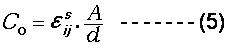
where, A is the electrode area, d is the thickness of the blank, and ε is the dielectric constant of the corresponding crystal cut.

In practically, Co includes not only the static capacitance of plated quartz blank, but also the capacitance of conductive bonding material and the capacitance of housing itself.

(8) Drive Level
The drive level of a resonator is the amount of power dissipation, expressed in nanowatts, microwatts or milliwatts. Operating level is the suitable power range to assure proper start and maintain a steady state oscillation. Drive level should be operated at the minimum level to avoid long-term frequency drift and crystal fracture. Generally, the smaller the product is, the lower the drive level should be applied without damanging the quartz resonators for long term usage. Generally, the drive level from 10μW to 100 μW is good enough for most of the applications.

(9) Quality Factor-Q
As a resonator, quality factor-Q value is a very important parameter. In specification, unloaded and loaded Q values are specified. The unloaded Q, or mechanical Q, can be expressed by

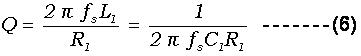
where, R1 is the resistance appearing in the series branch.

The loaded Q value depends on the loaded circuit.

(10) Pullability
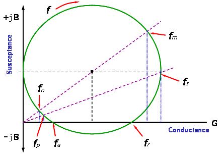
In a parallel-load capacitance oscillator, the oscillation frequency depends on the load capacitance, CL as shown in Eq.(3) and (Fig. 11). The frequency change (in ppm) as a function of the load capacitance change (in pF) is a specification. In certain applications where the variation of loaded resonance frequency is mandatory (VCXO, for example), pullability has to be specified.

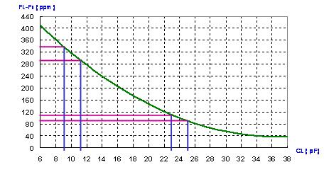
(Fig.11) Frequency variation vs. load capacitance

(11) AGING
Aging is the relative change of operating frequency over a specified time period and is expressed in parts per million (ppm) within a specified period. This rate of frequency change is normally exponential in character. The highest aging rate occurs within the first week of aging and decreases slowly after wards. Typically, aging is computed within first 30 days and is calculated over a long-term period (one year or ten years). Aging rate depends on many factors: seal method, integrity, manufacturing processes, material type, operating temperature, and frequency.

(12) STORAGE TEMPERATURE RANGE
The specification indicates the minimum and maximum temperatures in which the devices can be stored or exposed in a non-operating state. After storing or exposing the devices at the specified temperature range for a long time, all of the specifications are guaranteed over the specified operating temperature range.

(13) Negative Resistance "-R"
Negative resistance is introduced to describe the electric property of an oscillator circuit, This is the amount of resistance that the oscillator circuit exhibits when looking into the circuit through the terminals of the resonator. One of the basic oscillation conditions demands the amplifier have to supply enough gain to compensate the loss in the resonator. From resonator point of view, the load has to exhibit enough "negative resistance" to compensate the resistance of the resonator. This is an important parmeter in designing oscillators.

(9) OSCILLATORS

All rights reserved© Shijiazhuang Seva Electronics Technology Co., Ltd